Magnetic stripe reader circuit
by Luis Padilla Visd¾mine
RequirementsTo read magnetic stripes with this design you will need a magnetic head, two transistors, a few resistors and capacitors, a 12 Volts DC power supply, a computer (with a C compiler) to decode the data and some soldering skills. A voltmeter and an oscilloscope are highly advisable while adjusting and testing the circuit. Maybe you can substitute the scope with a sound card if it can digitalize fast enough.
The magnetic head has to be chosen such that the size of the track matches that of the magnetic stripe. I found that the size of the track of a normal mono audio cassette player is a little bit smaller than required but it works well. Using a stereo audio head it is not recommended unless you want to read two tracks at a time, but I have not checked if the separation of the audio tracks is the same than that of the data tracks.
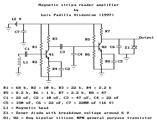
Circuit descriptionThe weak signal from the magnetic head has to be amplified in order to drive an input port of the computer. For that reason you will need a circuit like the one in the figure (or a similar one) which is basically an amplifier. The transistor Q1 acts like a preamplifier, raising the weak head signal, under 1 mV, to the level of tenths of volts. As a preamplifier, it has a low noise factor; this is achieved through operating the transistor at low current (under 1 mA) and low voltage (under 2 V).
The transistor Q2 acts like an amplifier and a driver for the input port of the computer. For that reason its output is connected directly, without any capacitor, to the input port of the computer. Therefore the DC voltage level of the transistor has to be adjusted to match the specifications of the port you are using. Both transistors, Q1 and Q2, have to be normal silicon bipolar general purpose NPN transistors. The value of the electronic components is not critical, specially for capacitors. You can choose from what you already have, those which are closer to the ones in the drawing.
This circuit is designed to work with a 12 V DC power supply. You can use another one, but then you will have to change the value of the resistors to keep the work point of the transistors in the same place. You can obtain +12 V DC from the power supply of your PC, which also have +5 V DC. The power consumption of this circuit should be around 60 mW. If your power supply is stabilized (that is the case of the power supply of the computer) then you may remove the capacitor C7, otherwise you should use a value as big as possible. Pay attention on the voltage the capacitor is rated, it should be no less than 16 V. You should also pay attention on the polarity of this and the other capacitors. The terminal rated "-" must be connected to ground or closer to ground than the other terminal.
Adjusting the circuitYou can make the circuit as it is drawn in the figure and it should work. However, for optimum performance, it is advisable that R2 and R6 would be variable resistors of value around 20 kOhm and 2 kOhm respectively. Initially place the cursor of the resistors in the middle position, that is, to get around 10 kOhm and 1 kOhm respectively. Then, while swiping a magnetic stripe card, change slowly the value of R2 until you get a square wave signal with maximum amplitude and minimum noise. This can be easily done if you have an oscilloscope, if you have not, then you can connect a speaker to the output and try to do it by hearing, although its results may be unpredictable.
Once you have set R2 for optimum performance, you have to adjust R6 to the proper value. Use the voltmeter to measure the DC voltage at the output of the circuit. Then, NOT swiping any card, change slowly the value of R6 until the DC level of the output is somewhere between 4.0 and 4.5 Volts. This assumes that the input port of the computer you are going to use works with TTL levels, that is, 0 and +5 V. The ideal voltage of the output would be +5 V, but you have to take into account that while swiping a card the output of the amplifier is going to exceed this voltage. That is the reason why you should set a lower value than +5 V for the output of the amplifier when not reading any card.
AdvicesThe Zener diode Z1 is used to protect the port of the computer against an excessive raise of the voltage. Its inverse breakdown voltage should be between 5.5 and 6.5 Volts. If you cannot get a Zener diode with that characteristic, you can get the same effect with normal diodes. A normal silicon diode drops by around 0.6 V the voltage of a signal in the direct direction, therefore if you put 10 normal silicon diodes in series they behave in direct direction as a Zener diode with inverse breakdown voltage of 6 V in inverse direction. You can also use a combination of both types. If you have a Zener diode of 4 V you should put 3 normal diodes in series with the Zener diode to get a breakdown voltage of about 5.8 V. Remember, Zener diode has to be put in inverse direction and normal diodes in direct direction. If you still cannot get this protection with diodes, then you should set the DC voltage of the circuit, when not reading, to a lower value, for example, between 3.0 and 3.5 Volts. This gives you an extra margin of protection and still would drive correctly the port of the computer.
You should pay attention to correctly ground every part of the circuit, especially to high frequencies, that is the reason for the capacitors C4 and C6. Grounding is very important to get ride of noise. The metallic shielding of the magnetic head should be grounded. You could also put the circuit inside a metallic case and ground it. Connect the magnetic head to the circuit with a cable as short as possible to avoid noise pick up. You have to take into account that the vicinity of the computer is a (electrically) very noisy environment. You may even notice that the noise pick up is considerablily reduced if you are also grounded while swiping the card.
Mechanics of the readerIf you want to read magnetic stripes successfully, you should use a mechanical device to swipe cards stablily and reliablily. You can either swipe the card over the head or the head over the card. I chose the second method.
In this case you should attach the magnetic head (with the sensitive side downwards) to a piece of plastic, wood or something with a regular shape and a smooth surface. Then fix two strips (one at each side of the head) on a board as a rail in which the magnetic head can only move forward and backward (smoothly). Be aware to leave enough space between the board and the strips in order to introduce the card which is going to be read. Once you fix the card on the board, with its magnetic stripe running parallel to the strips, you can swipe the head along the card easily. Now you only have to move in small steps the position of the card until you find the track to be read. You know that the track is caught when the signal from the amplifier is a perfect square wave with maximum amplitude and minimum noise. As long as the majority of the cards follows the ISO standards, I suggest you to make some marks on the reader to sign the position of the tracks. So you don't have to repeat the whole process each time you want to read a card.
padilla@gae.ucm.es (13-Jan-98) My PGP public key.